
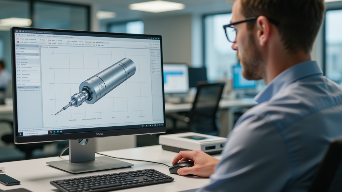
MU-Series Cradle Five-Axis Machining Center (MU-400V / MU-500V)
MU-series cradle five-axis machining centers finish multi-face and contoured parts such as impellers, molds and precision components in one clamping, using a rigid A/C trunnion table, simultaneous five-axis interpolation and tool-center-point control.
- CategoryCradle Five-Axis Machining Center
- 24-tool magazineMU400V-24
- 40-tool magazineMU400V-40
- MU-500V, 40-tool magazineMU500V-40
Price and lead time are quoted per configuration and quantity. Send us your part or capacity requirement and we will come back with a quotation.
Built for Complex, Multi-Face Geometry
The cradle five-axis machining center is intended for parts whose faces, angles and contoured features cannot be reached in a single three-axis setup: impellers, turbine and compressor components, medical constructions and precision molds. By tilting and rotating the workpiece on a trunnion, most of the part is finished with one tool orientation and one clamping.
The machine uses a simulated five-axis (3 + 2 tilt and rotate) architecture that keeps the structure rigid while still giving full access to compound angles.
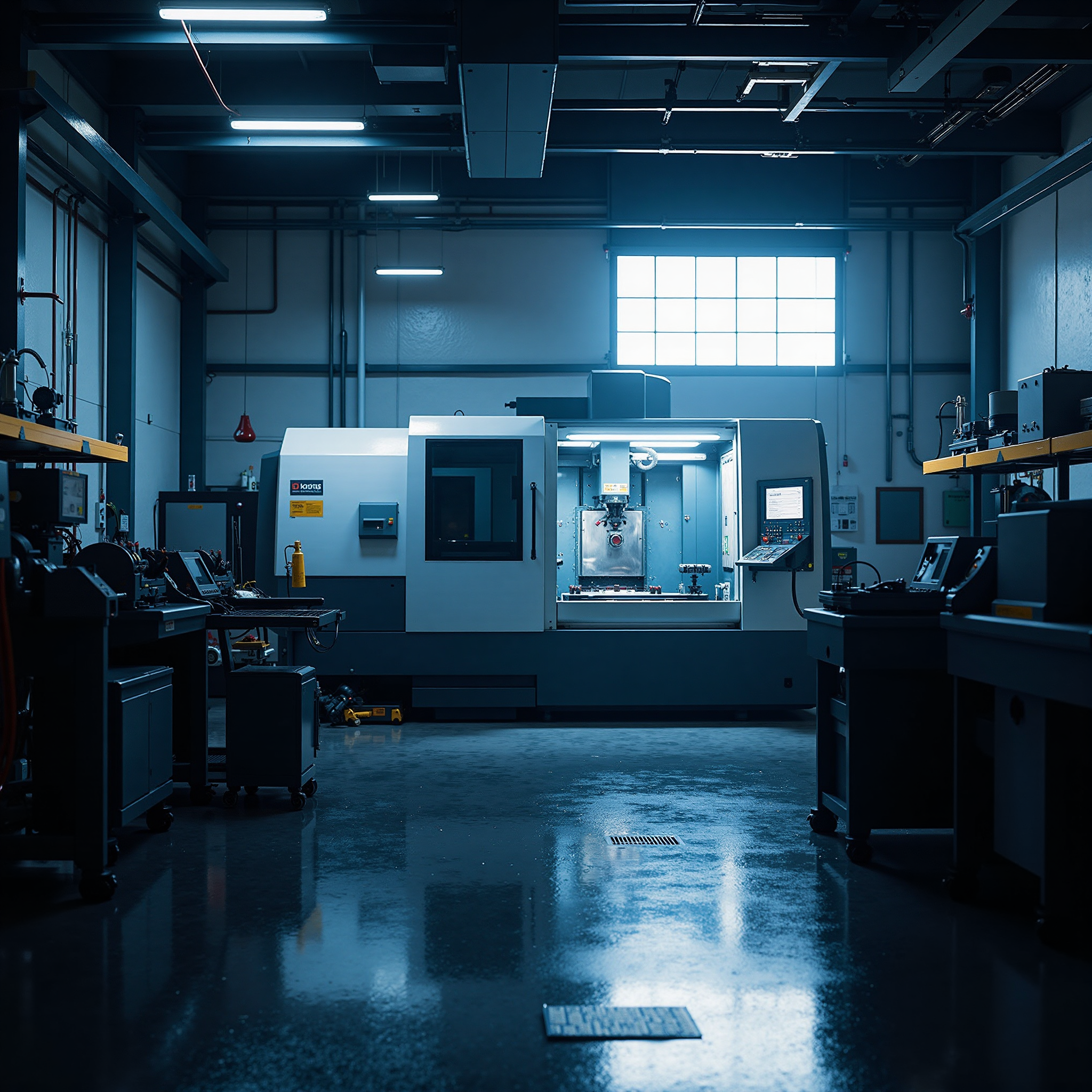
Cradle (Trunnion) and Rotary Axes
The A/C trunnion carries the table between two rigid uprights, and both rotary axes use direct or backlash-free gearing to hold angular position under cutting load. Clamping on both axes locks the table during heavy cutting on a compound face.
- A axis: tilting table, typical range -120 to +45 degrees for selection
- C axis: continuous rotation for contouring and drilling around the part
- Rotary drive: high-torque and backlash-free for stable multi-face machining
Accuracy and Thermal Behaviour
Box-in-box structural castings and cooled ballscrews reduce the influence of heat over long cycles. Geometric accuracy on a cradle machine is defined per axis as well as in the combined A/C orientation, so a full accuracy report covering both is worth requesting.
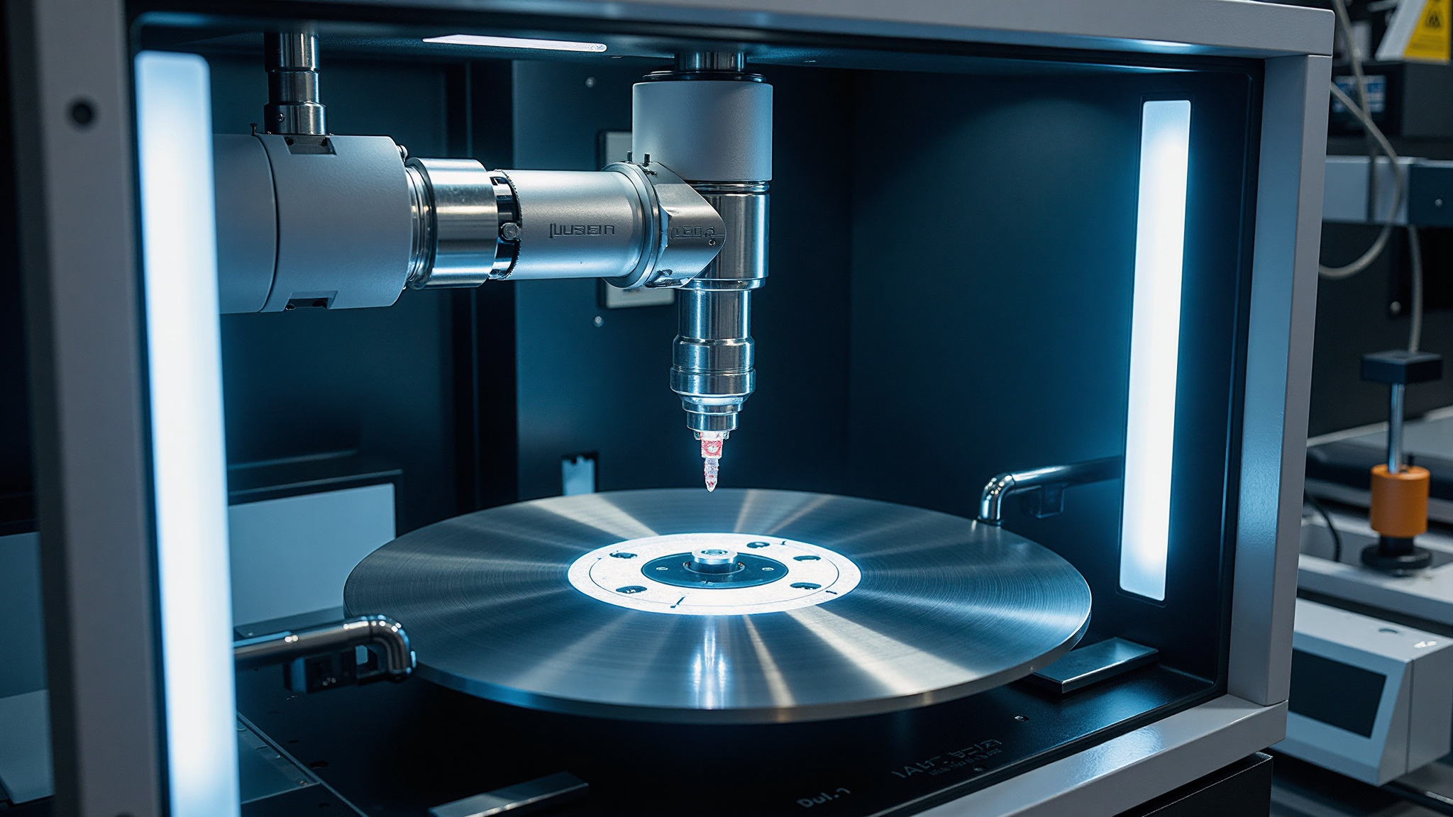
Control and Automation Options
The control supports simultaneous five-axis interpolation, RTCP and tool-center-point management so that programming effort does not grow with the number of tool orientations. Optional tool setting, in-process probing and pallet or robot interfaces support unattended runs.
Reference Specifications
Typical values are listed for selection reference; the final configuration and quotation are subject to inquiry confirmation.
| Item | MU-400V (typical) | MU-500V (typical) |
|---|---|---|
| Swing diameter | approx. 400 mm | approx. 500 mm |
| X/Y/Z travels | 600 x 500 x 450 mm | 700 x 600 x 500 mm |
| A / C axis | +/-120 deg / 360 deg continuous | +/-120 deg / 360 deg continuous |
| Spindle speed | up to 12,000 r/min | up to 12,000 r/min |
| Spindle taper | HSK-A63 / BT40 | HSK-A63 / BT40 |
| Tool magazine capacity | 24 / 40 stations | 24 / 40 stations |
| Positioning accuracy | approx. +/-0.005 mm | approx. +/-0.005 mm |
| Rotary indexing accuracy | approx. +/-10 arc-sec | approx. +/-10 arc-sec |
| Spindle motor power | approx. 11 / 15 kW | approx. 15 / 18.5 kW |
Selection Notes
Match swing diameter and maximum part weight first, then set the rotary indexing accuracy against your tightest tolerance callout. Where high-speed aluminum work dominates, consider the higher spindle-speed option; for mold work in hard materials, choose the higher-torque spindle.
Acceptance Points
Verify a five-axis test cut for tool-center-point behaviour, measure the actual A/C angular error and roundness on a sample impeller or mold insert, and confirm thermal stability over a long run before signing off.
Need a Different Configuration?
Tell us the parts you machine and the batch size — we will recommend a machine or process that fits.